3.8. Edge-Edge communication via Repeater
3.8.1. Background
This tutorial will move one step further from the previous tutorial Edge-Cloud communication on WAN. It is recommended to follow these tutorials in order, as some concepts or installations may be already covered. It will focus on an edge-edge architecture in which both edge robots are deployed on different networks (WAN) with access to the Internet, and communicate through a server hosted in the Cloud.
The scenario we are considering in this tutorial is the one where the edges are not directly connected (are under different LANs) and each robot does not have access to the other’s location and network (as they may be behind intermediate NATs or be part of dynamic networks). In this scenario, the Cloud server will work as a TURN (Traversal Using Relays around NAT), a.k.a Repeater. This kind of servers are meant to be accessed from every point in the WAN network, and forward the messages received from any edge to the rest of devices connected to the server. Thus, it creates a bridge between 2 networks that do not have direct access to each other, facilitating network configuration aspects such as NATs Traversals and dynamic addresses.
Warning
This tutorial is intended for WAN communication.
However, if communication through a LAN is your only option, it is still possible to follow the tutorial by changing the ROS 2 Domain Ids so that each edge uses a different Domain (0 and 1).
This way the ROS 2 nodes are logically isolated and will not discover other nodes out of their ROS 2 Domain.
Following, all the elements involved in this architecture will be studied, starting with the edge robots and continuing with the intermediate elements that enable communication over the Internet between each edge and the Cloud. One edge will work as a controller and the other as a robot (as already explained in previous tutorial).
The image below describes the scenario presented in this tutorial.
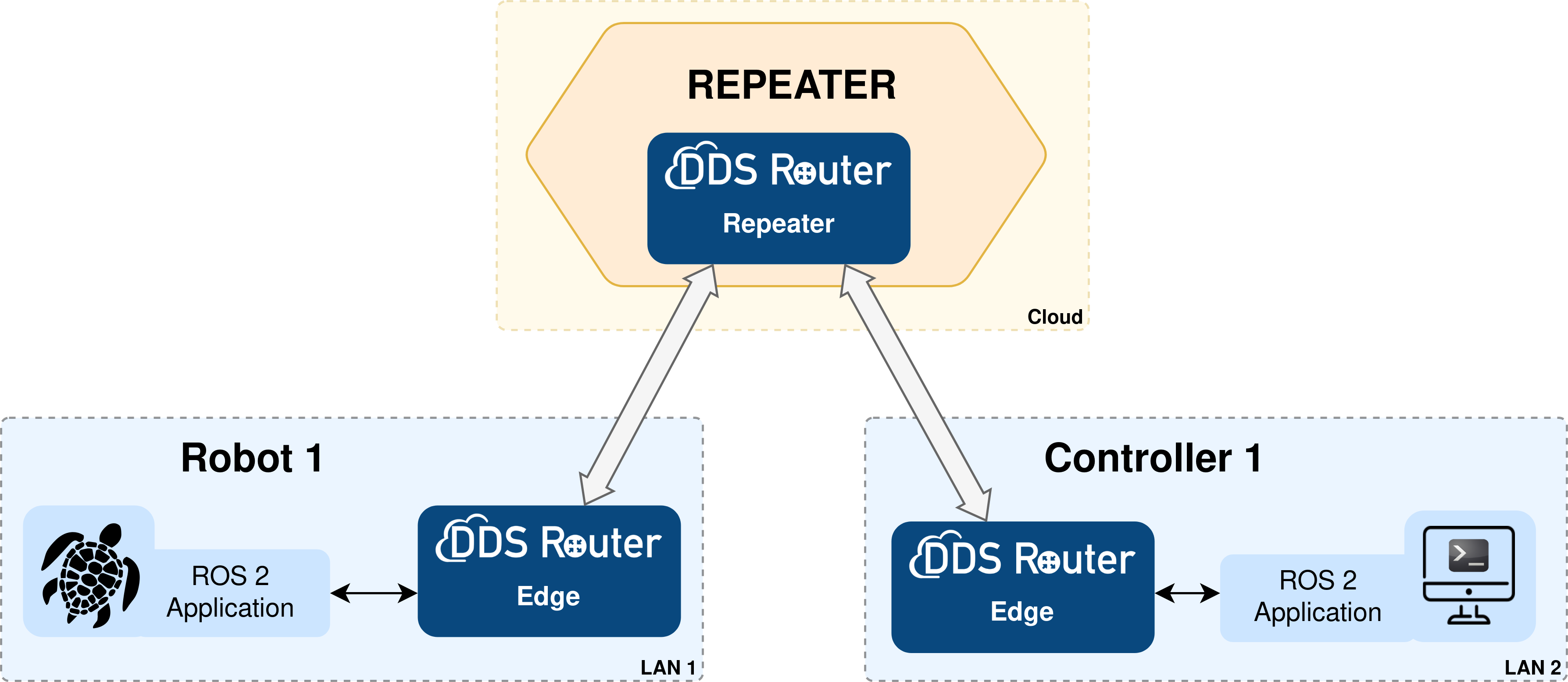
Several key elements can be observed in it:
ROS 2 Application. Turtlesim is the application used for this tutorial. Turtlesim is a ROS 2 application, first developed for ROS, aimed at teaching the basic concepts of ROS 2 such as publish/subscribe, services and actions. The edge robot will then be a
turtlesim_node, which is a simulator of a robot making use of these communication methods.ROS 2 Controller. A basic C++ application has been developed for this tutorial that sends publications under the topic on which the
turtlesim_nodelistens. It has been developed a basic C++ application for this tutorial that sends publications on the topic that theturtlesim_nodelistens. By means of these publications (commands) from the controller, and the feedback information that the controller receives from theturtlesim_node, it is possible to control this node automatically without the need for user intervention which facilitates the deployment of the scenario at hand. The key feature of the DDS Router is that it is easy to configure, allowing to connect different networks with ROS 2 applications without requiring to apply any changes to the developer’s software or applications.ROS 2 Router / DDS Router. eProsima ROS 2 Router, a.k.a DDS Router, is an end-user software application that enables the connection of distributed ROS 2 networks (see DDS Router documentation here). That is, ROS 2 nodes such as publishers and subscribers, or clients and services, deployed in one geographic location and using a dedicated local network will be able to communicate with other ROS 2 nodes deployed in different geographic areas on their own dedicated local networks as if they were all on the same network through the use of DDS Router.
This example presents two routers that enable Internet communication:
DDS Router Edge. This is the DDS Router that is deployed on the edge robot side. This way it is possible for the robot to communicate out-of-the-box with an external server.
DDS Router Repeater. It plays the TURN server role in the communication. It will expose some public network addresses to which the edge Routers could establish communication, and will forward the messages from one LAN to the other.
3.8.2. Prerequisites
This tutorial will require three machines (Robot 1, Controller 1 and Cloud Server) deployed on different networks (LAN 1, LAN 2 and Cloud). It is possible to simulate the scenario by deploying everything needed on the same machine and three virtual networks but let’s focus on the case of a real deployment.
It is also necessary to have previously installed Vulcanexus using one of the following installation methods:
3.8.3. Deployment on LAN 1
First, let’s deploy the turtlesim_node and DDS Router Edge on a machine on LAN 1.
3.8.3.1. Running turtlesim_node on Edge 1
Setup the Vulcanexus environment to have the turtlesim_node available.
For this, there are two possible options:
Running the Vulcanexus Docker image.
Run the Vulcanexus Docker image with:
xhost local:root
docker run \
    -it \
    --privileged \
    -e DISPLAY=$DISPLAY \
    -v /tmp/.X11-unix:/tmp/.X11-unix \
    ubuntu-vulcanexus:humble-desktop
Then, within the container, source the Vulcanexus installation with:
source /opt/vulcanexus/humble/setup.bash
Setting up the development environment on the local host. For this second option, it is necessary to have installed the
vucanexus-humble-desktoppackage, since this is the one that includes all the simulation tools, demos and tutorials.Source the following file to setup the Vulcanexus environment:
source /opt/vulcanexus/humble/setup.bash
Once the environment has been setup using one of the above options, simply run the turtlesim_node.
ros2 run turtlesim turtlesim_node
And a popup window like the following should appear:
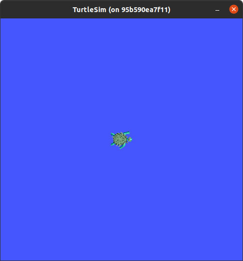
As can be seen, it is not necessary to perform any additional configuration in the ROS 2 application.
3.8.3.2. Running DDS Router Edge 1
Then, to run the DDS Router Edge configure the environment as in the previous step.
Note
If deploying Vulcanexus from the Docker image, note that you will need to have a configuration file (config.yaml) for the DDS Router Edge accessible from your Docker container.
This can be achieved by mounting a shared volume when launching the container, by copying the file from the local host to the container in case it is already running, or by editing a file from the Docker container itself.
Setup the Vulcanexus environment, either in a Docker container or on the local host, running the following command:
source /opt/vulcanexus/humble/setup.bash
Let’s create a the DDS Router configuration file as the one shown below.
version: v3.1

participants:

  - name: ROS_2_LAN_1
    kind: local

  - name: Router_Client
    kind: wan
    connection-addresses:
      - ip: 123.123.123.123
        port: 45601
        transport: tcp
Next, the most relevant aspects of this configuration file are explained.
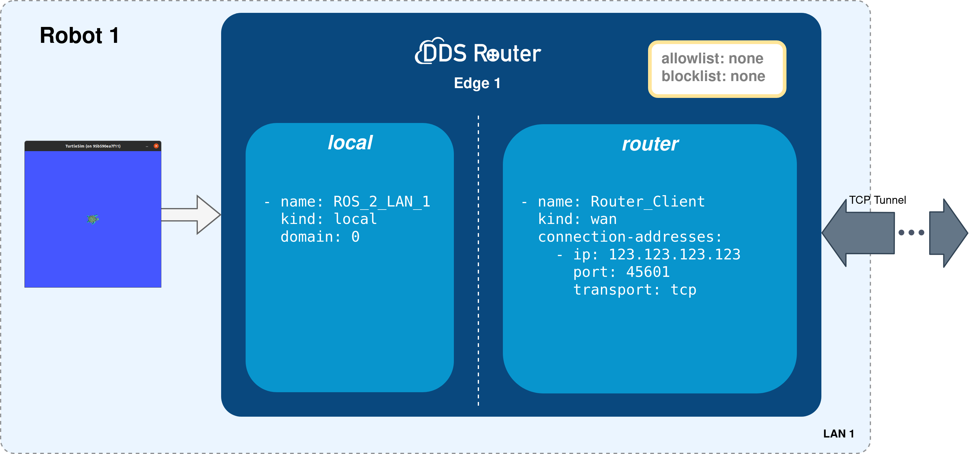
The participants are the interfaces of the DDS Router to communicate with other networks. In this case, we have two kinds of participants:
local: this is a simple participant that communicates with all ROS 2 nodes it finds in domain 0. For more information about this participant please refer to the Simple Participant section of the DDS Router documentation.
wan: it is a participant designed to communicate with a WAN Participant configured as server (repeater in this case). It uses the Initial Peers discovery mechanism to establish a point-to-point communication between two DDS entities, two DDS Routers in this case.For the DDS Router Edge, a connection address shall be defined which must be the same as the one exposed by the Cloud Server.
Note
In this case, the DDS Router will forward all topics found in the network.
However, it is important to mention that the ROS 2 topics relayed by the DDS Router can be filtered by configuring the allowlist and blocklist.
If this is the case please refer to the DDS Router documentation for information on how to do this.
The following figure summarizes the deployment on the edge 1.
Now, run the DDS Router with the configuration file created as an argument.
ddsrouter -c <path/to/file>/ddsrouter_edge_1.yaml
3.8.4. Deployment of LAN 2
3.8.4.1. Running the turtlesim_square_move on Edge 2
Run the turtlesim_square_move in the Edge 2 machine, which is the controller of the Edge 1 turtlesim_node.
This will send commands to the ROS 2 application to the edge to move the turtle and receive information about the current state of the turtle at any time.
A ROS 2 application that moves the turtle by drawing a square has been developed for this purpose. The application is based on the ROS 2 tutorials, but has been slightly modified in order to make it easier to understand and adapt to the ROS 2 and modern C++ programming methods.
Then, start by creating the workspace of this application and downloading the source code:
mkdir -p turtlesim_move_ws/src && cd turtlesim_move_ws/src
git clone --branch humble https://github.com/eProsima/vulcanexus.git
mv vulcanexus/code/turtlesim .
rm -rf vulcanexus
cd ..
Once created the workspace, source the Vulcanexus environment and build the turtlesim_square_move application.
source /opt/vulcanexus/humble/setup.bash
colcon build
Note
Since the purpose of this tutorial is not to explain how to create a ROS 2 node, but rather, the communication of these in distributed environments, the code will not be discussed in detail. Stay tuned for new tutorials in which we will discuss how to configure ROS 2 nodes, publishers/subscribers, services and actions.
Then source the turtlesim_move_ws workspace:
source turtlesim_move_ws/install/setup.bash
And finally, run the application:
ros2 run docs_turtlesim turtlesim_square_move
ROS_DOMAIN_ID=1 ros2 run docs_turtlesim turtlesim_square_move
Note
As stated here, change the ROS 2 Domain Id if running the edge and cloud applications on the same LAN.
The important points to note in this application are the following:
The control application sends the movement commands to the
turtlesim_nodethrough a publisher in the geometry_msgs/msg/Twist topic. This topic expresses the velocity at which the turtle has to move divided into linear velocity (linear) and angular velocity (angular).The application knows the position of the turtle on the map at any moment and whether it is stopped or moving by subscribing to the turtlesim/msg/pose topic. This topic provides information about the turtle’s coordinates (
xandy) and the turtle’s rotation (theta). We can also know its linear and angular velocity (linear_velocityandangular_velocity).
3.8.4.2. Running DDS Router Edge 2
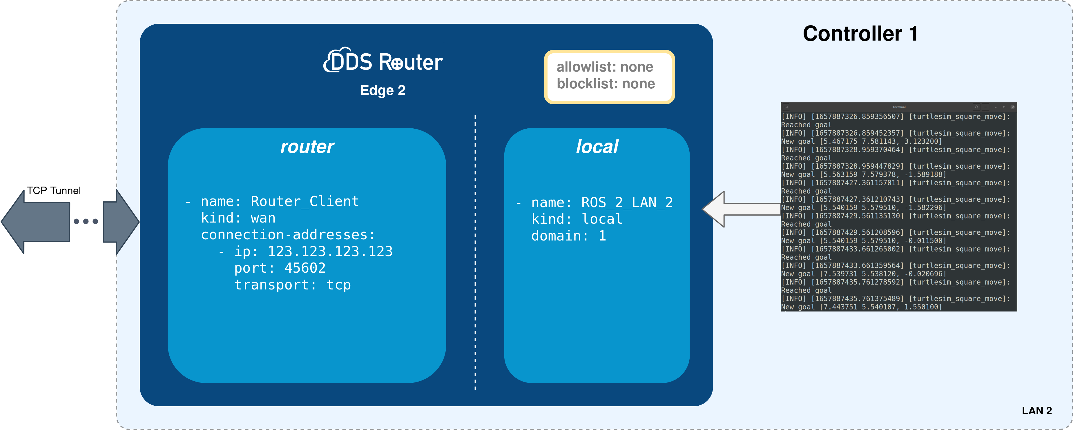
As the Repeater server is the same for both edges, the configuration of the DDS Router Edge 2 is very similar to the one for the DDS Router Edge 1. In this example both edges use different ports to communicate with the Repeater, simulating 2 different networks available in the Cloud. However this is not needed, and only one address could be used. The following snippet shows a configuration file (changing Domain for LAN scenarios):
version: v3.1

participants:

  - name: ROS_2_LAN_2
    kind: local

  - name: Router_Client
    kind: wan
    connection-addresses:
      - ip: 123.123.123.123
        port: 45602
        transport: tcp
version: v3.1

participants:

  - name: ROS_2_LAN_2
    kind: local
    domain: 1

  - name: Router_Client
    kind: wan
    connection-addresses:
      - ip: 123.123.123.123
        port: 45602
        transport: tcp
Note
As stated here, set the ROS 2 Domain Id on the local participant in order to discover the turtlesim_square_move ROS 2 node.
Now, run the DDS Router with the configuration file created as an argument.
ddsrouter -c <path/to/file>/ddsrouter_edge_2.yaml
The following figure summarizes the deployment on the edge 2.
3.8.5. Deployment of Cloud Repeater
In order to communicate both edges, a DDS Router configured as Repeater is used, forwarding the messages from one edge to the other. This machine should be accessible from the Internet. In case this device is working under a NAT, check previous tutorial for more information about how to configure the NAT to be accessible from the outside. The following snippet shows the configuration file for this DDS Router:
version: v3.1

participants:

  - name: Router_Repeater
    kind: wan
    repeater: true
    listening-addresses:
      - ip: 123.123.123.123
        port: 45601
        transport: tcp
      - ip: 123.123.123.123
        port: 45602
        transport: tcp
In this case, there is only one Participant configured as repeater.
This Participant will wait for external Participants to communicate via Initial Peers from its listening-addresses.
Once the discovery of clients occurs, this Repeater will forward the data from one edge to the other.
To run the DDS Router with the configuration file created as an argument, execute the following command after having sourced the Vulcanexus environment:
ddsrouter -c <path/to/file>/dds_router_repeater.yaml
Note
The Repeater Participant is not limited by number of listening-addresses, neither by number of edge Routers. It can open as many ports and interfaces as needed, and can forward messages from any number of edges, without re-sending redundant information or sending back any message.
3.8.6. Results
If all the steps in this tutorial have been followed, the turtle in the turtlesim_node on the edge should move around creating a square,
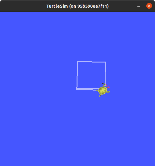
and the turtlesim_square_move should prompt the following traces
root@dbf79a437eb3:/turtlesim_move_ws# ros2 run turtlesim turtlesim_square_move
[INFO] [1657870899.585667136] [turtlesim_square_move]: New goal [7.544445 5.544445, 0.000000]
[INFO] [1657870901.585656311] [turtlesim_square_move]: Reached goal
[INFO] [1657870901.585767260] [turtlesim_square_move]: New goal [7.448444 5.544445, 1.570796]
[INFO] [1657870905.685637930] [turtlesim_square_move]: Reached goal
[INFO] [1657870905.685753714] [turtlesim_square_move]: New goal [7.466837 7.544360, 1.561600]
[INFO] [1657870907.885655744] [turtlesim_square_move]: Reached goal
[INFO] [1657870907.885742857] [turtlesim_square_move]: New goal [7.466837 7.544360, 3.132396]
[INFO] [1657870911.985655175] [turtlesim_square_move]: Reached goal
[INFO] [1657870911.985738726] [turtlesim_square_move]: New goal [5.467175 7.581143, 3.123200]
[INFO] [1657870914.085652821] [turtlesim_square_move]: Reached goal