3.9. Cloud ROS 2 MicroServices
3.9.1. Background
This tutorial will cover how to deploy a Cloud Micro Service architecture using Vulcanexus. Specifically, it will be shown how to deploy ROS 2 services in a Cloud device and access them from Node Clients in different edges. The idea is to maintain an out-of-the-box ROS 2 group of services accessible from any location and capable of executing high performance tasks, thus reducing the computational effort made by the edge nodes.
Warning
This tutorial is intended for WAN communication.
However, if communication through a LAN is your only option, it is still possible to follow the tutorial by changing the ROS 2 Domain Ids so that each ROS 2 node uses a different Domain (0 and 1).
This way the ROS 2 nodes are logically isolated and will not discover other nodes out of their ROS 2 Domain.
Note
This tutorial uses the ROS 2 Service communication method. Refer to ROS 2 Documentation for more information regarding ROS 2 Services, how they work and how to use them.
Following, all the elements involved in this architecture will be studied, starting with the edge robot, continuing with the controller hosted in the cloud also built as a ROS 2 node and concluding with the intermediate elements that enable communication over the Internet.
The image below describes the scenario presented in this tutorial.
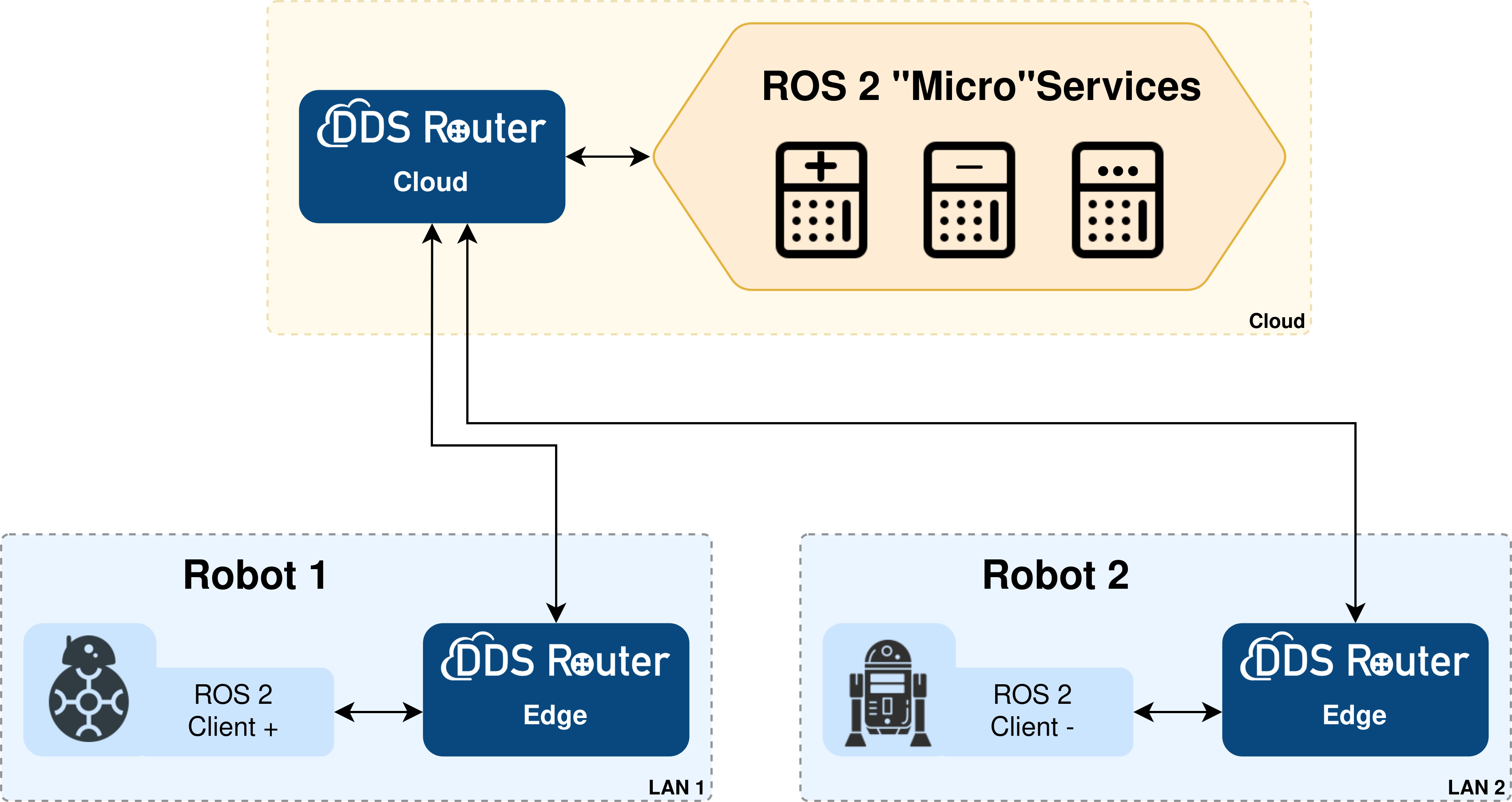
Several key elements can be observed in it:
ROS 2 Application. The application used for this tutorial are trivial ROS 2 clients. These clients will connect to ROS 2 Services hosted in Cloud. This example will focus on
Robot 1that will connect to services+and-.ROS 2 “Micro” Services. This ROS 2 application will handle several ROS 2 servers, each providing a different service. Two basic Python applications have been developed for this tutorial, representing the server and client nodes in a service, which is nothing more than a solver of trivial mathematical operations. The functionality of the services is not relevant for this tutorial, they are only meant to exemplify a micro-service architecture. In the actual deployment of this architecture, the services could manage any kind of task. The services implemented are:
additiona.k.a.+adds two integer numbers.subtractiona.k.a.-subtracts two integer numbers.
ROS 2 Router / DDS Router. eProsima ROS 2 Router, a.k.a DDS Router, is an end-user software application that enables the connection of distributed ROS 2 networks (see DDS Router documentation here). That is, ROS 2 nodes such as publishers and subscriptions, or clients and services, deployed in one geographic location and using a dedicated local network will be able to communicate with other ROS 2 nodes deployed in different geographic areas on their own dedicated local networks as if they were all on the same network through the use of DDS Router.
This example presents two routers that enable Internet communication:
DDS Router Edge. This is the DDS Router that is deployed on the edge robot side. This way it is possible for the robot to communicate out-of-the-box with an external server.
DDS Router Cloud. It plays the server role in the communication. It will expose a public network address to which the nodes connect to establish communication.
Warning
ROS 2 Services are (in principle) not meant to be provided by more than one node in the same network. The use of multiple servers on the same Service will result in a very low-performance system, as messages will be received and processed by every server.
The number of different services that could be hosted in the Cloud is not limited. The number of clients able to reach those servers is also unlimited, as well as the services that each device handles (edge or Cloud), allowing the same ROS 2 application to serve as a client or server of multiple services.
3.9.2. Prerequisites
This tutorial will require at least two machines (Robot 1 and Cloud Server) deployed on different networks (LAN 1 and Cloud). In order to recreate a more realistic scenario, there could be as many edge robots as desired without additional configurations. It is possible to simulate the scenario by deploying everything needed on the same machine and two virtual networks, but let’s focus on the case of a real deployment.
It is also necessary to have previously installed Vulcanexus using one of the following installation methods:
3.9.3. Deployment on LAN 1
First, let’s deploy the Client and DDS Router Edge on a machine on LAN 1.
3.9.3.1. Running Robot 1 on the edge
Run any of the clients for the ROS 2 Services in this machine.
This will publish Request messages to every server listening in the network.
Once the whole network has been established, those messages will arrive to the server hosted in cloud, and will answer with a Response.
In this tutorial, an example on how to implement some of these services (for servers and clients) is provided. Following are the ones used in this example, however the implementation of new and complex ones is straight-forward:
addition_service
Client: generate 2 random numbers from 0 to 100 and send request to server. Command:
ros2 run clients_py client_additionServer: add 2 integers get in request, and send solution in response. Command:
ros2 run microservers_py server_additionsubtraction_service
Client: generate 2 random numbers from 0 to 100 and send request to server. Command:
ros2 run clients_py client_subtractionServer: subtract 2 integers get in request, and send solution in response. Command:
ros2 run microservers_py server_subtraction
These files can be found at code/microservices in Vulcanexus Documentation Repository as a Colcon python package.
In order to install these applications, follow these steps:
Start by creating the workspace of this application and downloading the source code:
mkdir -p clients_ws/src && cd clients_ws/src
git clone --branch humble https://github.com/eProsima/vulcanexus.git
mv vulcanexus/code/microservices/clients_py .
rm -rf vulcanexus
cd ..
Once created the workspace, source the Vulcanexus environment and build the clients_py package.
source /opt/vulcanexus/humble/setup.bash
colcon build
Then source the clients_ws workspace:
source install/setup.bash
And finally, run the application:
ros2 run clients_py client_addition # client_subtraction
Note
Since the purpose of this tutorial is not to explain how to create a ROS 2 node, but rather, the communication of these in distributed environments, the code will not be discussed in detail. This code has been developed following this ROS 2 tutorial and the comments along the code make it self-explanatory. Stay tuned for new tutorials where we will discuss how to configure ROS 2 nodes, publishers/subscribers, services and actions.
3.9.3.2. Running DDS Router Edge
Then, to run the DDS Router Edge configure the environment as in the previous step.
Note
If deploying Vulcanexus from the Docker image, note that you will need to have a configuration file (config.yaml) for the DDS Router Edge accessible from your Docker container.
This can be achieved by mounting a shared volume when launching the container, by copying the file from the local host to the container in case it is already running, or by editing a file from the Docker container itself.
Setup the Vulcanexus environment, either in a Docker container or on the local host, running the following command:
source /opt/vulcanexus/humble/setup.bash
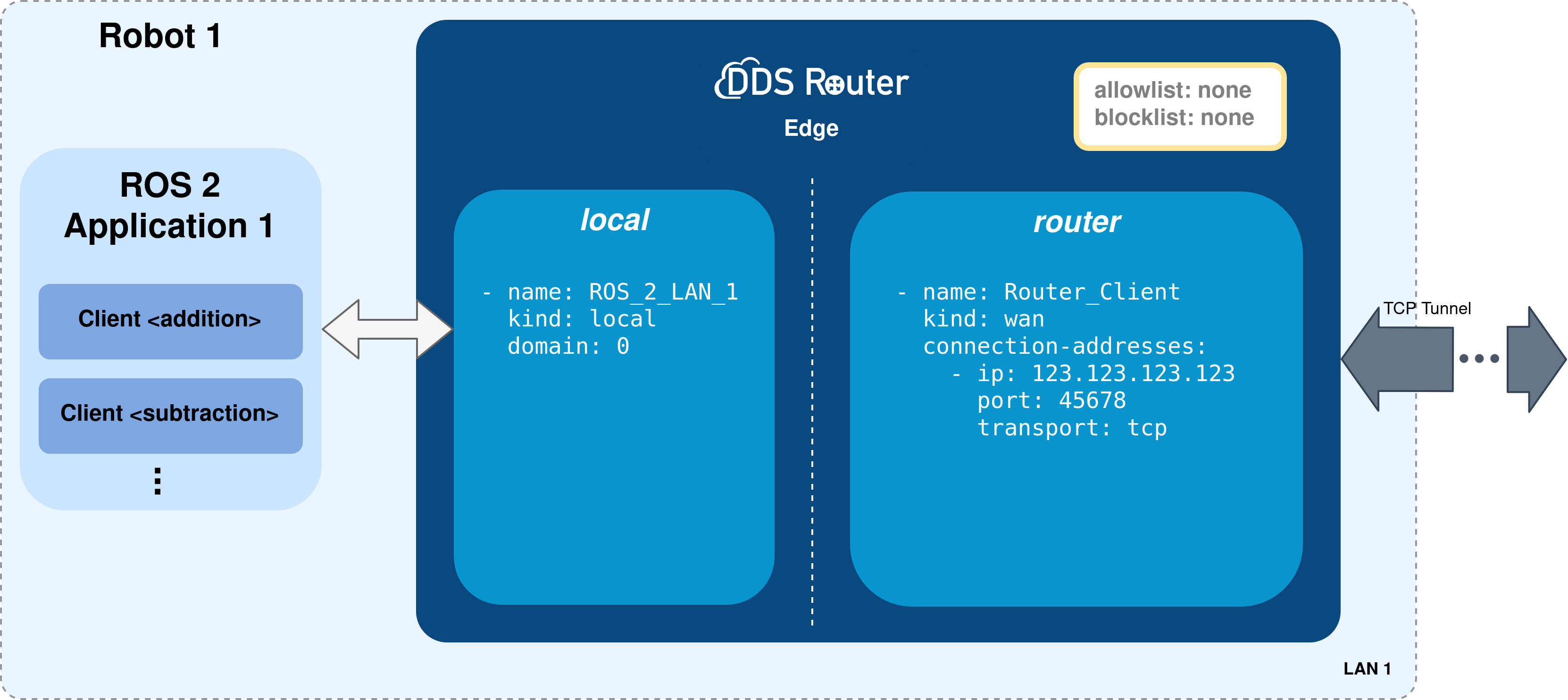
Let’s create a DDS Router configuration file as the one shown below.
version: v3.1

participants:

  - name: ROS_2_LAN_1
    kind: local

  - name: Router_Client
    kind: wan
    connection-addresses:
      - ip: 123.123.123.123
        port: 45678
        transport: tcp
Next, the most relevant aspects of this configuration file are explained.
The participants are the interfaces of the DDS Router to communicate with other networks. In this case, we have two kinds of participants:
local: this is a simple participant that communicates with all ROS 2 nodes it finds. For more information about this participant please refer to the Simple Participant section of the DDS Router documentation.
wan: it is a participant designed for the communication between two DDS Routers. It uses the Initial Peers discovery mechanism to establish a point-to-point communication between two DDS entities, two DDS Routers in this case.For the DDS Router Edge, a connection address shall be defined which must be the same as the one exposed by the Cloud Server.
Note
In this case, the DDS Router will forward all topics found in the network.
However, it is important to mention that the ROS 2 topics relayed by the DDS Router can be filtered by configuring the allowlist and blocklist.
If this is the case please refer to the DDS Router documentation for information on how to do this.
The following figure summarizes the deployment on the edge.
To finish this step, run the DDS Router with the configuration file created as an argument.
ddsrouter -c <path/to/file>/ddsrouter_edge.yaml
3.9.3.3. Running more than one Edge
Several edge robots can be deployed on the same scenario without affecting the functionality or configuration.
Robot 2 shown in figure could be deployed using the exact configuration used for Robot 1.
The services that each Robot connects to could be configured in the ROS 2 application running in each device.
The scenario is not dependent on the ROS 2 Services in the network, neither the clients or servers running.
This is a very flexible and scalable scenario.
3.9.4. Deployment on Cloud
3.9.4.1. Running Services on the Cloud
In order to install and use the MicroServers, follow the instructions in section Running Robot 1 on the edge
but use the package microservers_py instead of client_py (change these strings in every command).
Once the whole workspace has been installed and correctly sourced, each server could be run with the following commands:
ros2 run microservers_py server_addition # To run Addition (+) Server

# In different terminal or background
ros2 run microservers_py server_subtraction # To run Subtraction (-) Server
ROS_DOMAIN_ID=1 ros2 run microservers_py server_addition # To run Addition (+) Server

# In different terminal or background
ROS_DOMAIN_ID=1 ros2 run microservers_py server_subtraction # To run Subtraction (-) Server
Note
As stated here, change the ROS 2 Domain Id if running the edge and cloud applications on the same LAN.
3.9.4.2. Running the DDS Router Cloud
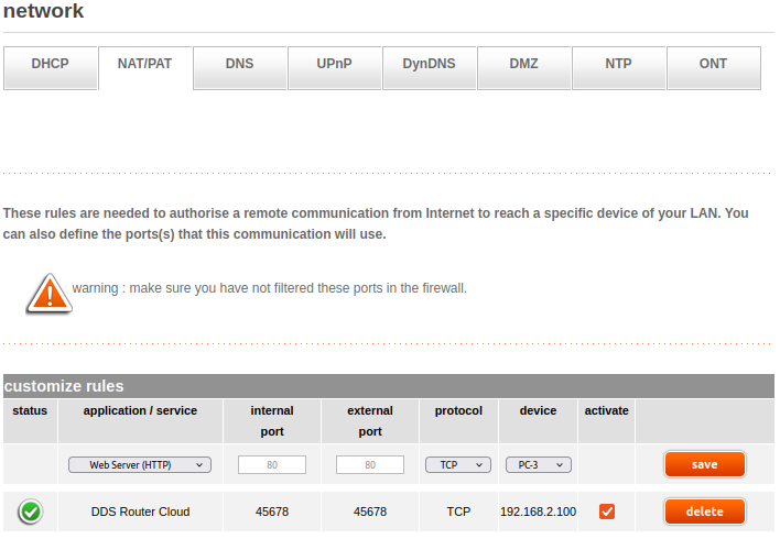
3.9.4.2.1. Configure transversal NAT on the network router
The first thing to do before starting to configure DDS Router is to configure the network router to allow a remote communication from the Internet to reach a specific device on the LAN, more specifically to expose an IP address and a port to the network that will be used by our DDS Router application.
This configuration will depend on your network router, but it should be similar to the one shown in the following image.
3.9.4.2.2. Configure the DDS Router Cloud
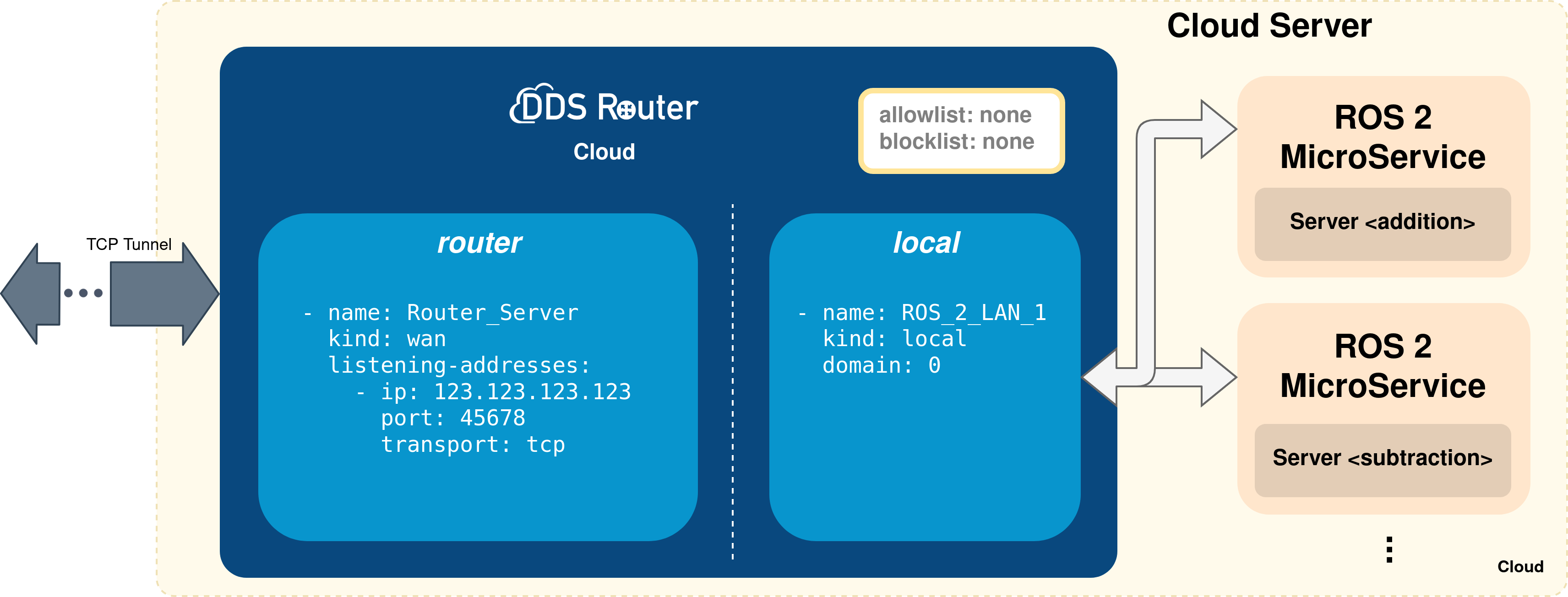
The DDS Router Cloud configuration file is quite similar to the DDS Router Edge configuration file, as can be seen below:
version: v3.1

participants:

  - name: ROS_2_Cloud
    kind: local

  - name: Router_Server
    kind: wan
    listening-addresses:
      - ip: 123.123.123.123
        port: 45678
        transport: tcp
version: v3.1

participants:

  - name: ROS_2_Cloud
    kind: local
    domain: 1

  - name: Router_Server
    kind: wan
    listening-addresses:
      - ip: 123.123.123.123
        port: 45678
        transport: tcp
Note
As stated here, set the ROS 2 Domain Id on the local participant in order to discover only those nodes required.
In this case there are also two participants, two communication interfaces for the DDS Router. The first one communicates the DDS Router with any ROS 2 node, while the second one enables to establish a communication channel with another DDS Router.
Although quite similar to the WAN participant in the DDS Router Edge instance, notice that this participant sets a listening address (listening-addresses), rather than a connection address.
This is because it is the participant that waits for incoming communications since it has this network address exposed and accessible from the Internet.
To finish, as done in the previous steps, setup the Vulcanexus environment sourcing the setup.bash file and run the DDS Router Cloud with the above configuration.
source /opt/vulcanexus/humble/setup.bash
ddsrouter -c <path/to/file>/ddsrouter_cloud.yaml
The following figure summarizes the deployment on the Cloud.
3.9.5. Results
If all the steps in this tutorial have been followed, each client running in an edge will print in stdout messages such as the following one:
root@dbf79a437eb3:/clients_ws# ros2 run clients_py client_addition
[INFO] [1659078463.756352817] [AdditionMicroClient]: Service not available, waiting again...
[INFO] [1659078528.309955103] [AdditionMicroClient]: Request sent, waiting for server result.
[INFO] [1659078530.288999295] [AdditionMicroClient]: Result of operation: for 63 + 40 = 103
While in the server side, messages as the one shown below should be printed:
root@dbf79a437eb3:/turtlesim_move_ws# ros2 run microservers_py server_addition
[INFO] [1659078530.288140374] [AdditionMicroServer]: Incoming request { 63 + 40 = 103 }